A Robust 4-Antenna Phasing System Using Independent 200↔50 Ω Transformers (Hard 4:1 Power Splitter)
1. Introduction
This document describes a robust 4‑antenna phasing system designed for the 14–30 MHz HF range. The system uses four independent Guanella UN‑UN transformers (200 ↔ 50 Ω) whose 200‑ohm sides are connected in parallel at the transmitter port. Each 50‑ohm side feeds one antenna through an equal‑length coaxial line, maintaining phase and amplitude balance.
The result is a “hard” 4:1 power splitter — a configuration that remains well‑matched and stable even when one or more antennas become detuned due to environmental or mechanical effects such as snow, ice, or element damage.
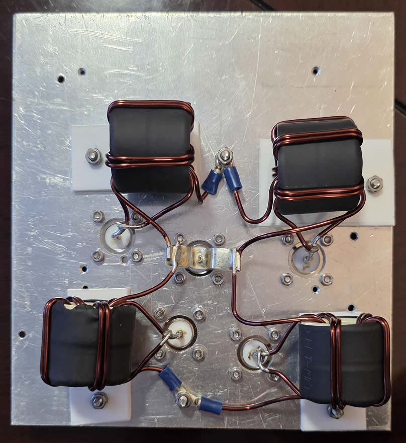
2. Transformer Construction
Each of the four transformers is built identically to ensure electrical symmetry:
• Core: Sky Sat FC260 or FT‑240‑61 ferrite cores (same type for all transformers)
• Winding: bifilar insulated copper wire, 2 mm diameter
• Turns: 5 turns per transformer
• Performance: all transformers tested using a VNA and showed identical matching (|S₁₁| ≈ –25 dB) across 14–30 MHz
Each antenna (50 Ω) is connected to the low‑impedance side. The four 200‑Ω sides are tied in parallel, providing approximately 50 Ω at the TX connector.
3. Analytical Calculation
In the ideal case, all four antennas present 50 Ω, each transformed to 200 Ω. Four 200‑Ω impedances in parallel yield 50 Ω, giving SWR = 1.00.
With measured return loss of 25 dB, |Γ| = 0.056 → SWR = 1.12.
If one antenna detunes to 30 Ω (transformed to 120 Ω), and the remaining three are 200 Ω each:
Z_eq = 1 / (1/120 + 3/200) = 46.15 Ω → SWR ≈ 1.08.
If two antennas detune to 30 Ω → 120 Ω each, and two remain 200 Ω:
Z_eq = 1 / (2/120 + 2/200) = 42.85 Ω → SWR ≈ 1.17.
Even with significant mismatch in one or two antennas, the system maintains excellent matching and balance — confirming its “hard” behavior.
4. Technical Interpretation
Each transformer handles one‑quarter of the total RF power, resulting in balanced current distribution and reduced core heating. Because every antenna is isolated by its own transformer, the coupling between antennas is minimized. The system tolerates impedance variations without significant change in overall matching, making it suitable for stacked or phased arrays in harsh environments.
5. Advantages Compared to a Single 4:1 Transformer
|
Feature |
4 × Independent 200↔50 Ω Transformers vs. Single 4:1 Transformer |
|
Symmetry |
Excellent (identical transformers) vs. fair symmetry in single transformer |
|
Fault tolerance |
Very high — one detuned antenna causes minimal effect |
|
Thermal load |
Distributed — ¼ total power per core |
|
Matching stability |
Very stable vs. mismatch‑sensitive |
|
Complexity |
Moderate vs. simpler single‑core system |
|
Efficiency |
High across 14–30 MHz HF range |
6. Conclusion
The 4‑antenna “hard” phasing system described here demonstrates excellent stability and reliability under real‑world conditions. By using four identical 200↔50 Ω transformers, the array maintains low SWR (≤ 1.2) even with substantial antenna impedance deviations. This distributed approach ensures both high efficiency and fault tolerance.
7. Receive Switching Option with 5‑Relay Control
An upgraded version of the 4‑antenna phasing system includes a relay‑based receive selection module, enabling single‑antenna reception while maintaining full four‑way transmission through the splitter during TX.
The module uses five RF relays:
• Four relays select individual antennas (ANT1–ANT4)
• One master relay switches between transmit (TX) and receive (RX) modes
Operating principle:
• Transmit mode (no control voltage / default):
All relays remain in their normally closed (NC) position, connecting all four transformers in parallel to the transmitter output. Power is evenly split among the antennas. This configuration is fail‑safe — if control voltage is lost, the system always returns to the full transmit mode.
• Receive mode (control voltage applied):
The master relay isolates the TX port and connects the receiver path. One of the four antenna relays is energized to connect only the selected antenna (50 Ω) to the receiver input, while the others are disconnected. Since impedance transformation is bypassed in RX mode, the receiver always sees a pure 50‑Ω load.
Fail‑safe behavior:
In case of power loss or control circuit failure, all relays revert to their NC state — restoring full 4‑way TX operation automatically.
Advantages:
• Fast switching between antennas for noise comparison or directionality
• No impedance shift in RX mode
• Full TX operation in default (fail‑safe) mode
• Compatible with standard 12/24‑V RF relays rated for HF service