A Robust 3-Antenna Phasing System Using Independent 150↔50 Ω Quadrifilar Transformers (Hard 3:1 Power Splitter with Relay Control)
1. Introduction
This article presents a robust and fault-tolerant phasing system for three identical antennas operating in the 14–30 MHz HF range. The system employs three independent quadrifilar UN‑UN transformers (150 ↔ 50 Ω) whose 150‑ohm sides are connected in parallel to the transmitter port. Each 50‑ohm side feeds one antenna through an equal‑length coaxial line, ensuring correct phase and amplitude balance.
The result is a “hard” 3:1 power splitter — a network that remains well‑matched and phase‑coherent even when one or more antennas become detuned due to snow, ice, or physical damage.
2. Transformer Construction
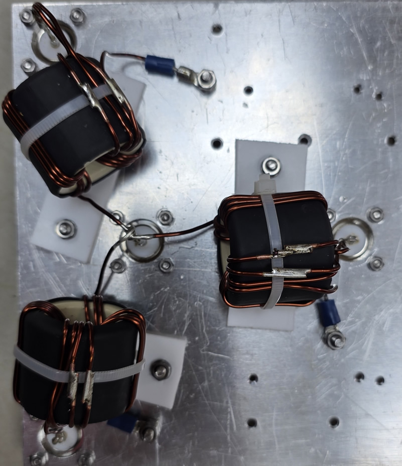
Each of the three transformers is wound in quadrifilar configuration, consisting of four parallel insulated copper wires wound simultaneously on a single ferrite core:
• Core: Sky Sat FC260 or FT‑240‑61 — same ferrite material for all units
• Winding: four insulated copper wires, each 2 mm diameter, wound together
• Turns: three wires make 4 turns, while the fourth wire makes 2 turns, as shown in the schematic (Fig. 1)
• Configuration: the shorter (2‑turn) winding forms the low‑impedance 50 Ω side, and the 4‑turn windings form the high‑impedance 150 Ω side
• Performance: all transformers tested on a VNA showed identical matching, |S₁₁| ≈ –25 dB across 14–30 MHz
Each antenna (50 Ω) is connected to the low‑impedance winding. The three 150‑Ω windings are tied in parallel to form a combined load of approximately 50 Ω toward the transmitter.
3. Analytical Calculation
The following analysis illustrates how the system behaves when one or more antennas are detuned — a common real‑world situation caused by broken elements, snow or ice accumulation, or moisture in the feed line.
In the ideal case, all three antennas present 50 Ω, transformed to 150 Ω each by their respective transformers. The three 150‑Ω windings in parallel yield a total load:
R_eq = 150 / 3 = 50 Ω → SWR = 1.00.
With the measured transformer return loss of 25 dB, |Γ| = 10^(–25/20) = 0.056 → SWR ≈ 1.12 — essentially a perfect match.
To assess system robustness:
• Case 1 – One antenna detuned:
One antenna changes to 30 Ω (e.g., due to ice or element damage). It is transformed to 90 Ω on the high‑impedance side. Two antennas remain 150 Ω. Z_eq = 41.0 Ω → SWR ≈ 1.22.
• Case 2 – Two antennas detuned:
Two antennas → 90 Ω each, one healthy → 150 Ω. Z_eq = 34.6 Ω → SWR ≈ 1.34.
These results demonstrate that the system remains well matched even with substantial impedance variations in one or two antennas — proof of its “hard” matching characteristic.
4. Technical Interpretation
Each quadrifilar transformer isolates its antenna from the others while maintaining phase coherence through equal coax lengths. Because each core handles only one‑third of the total power, magnetic and thermal stress are reduced. The use of a quadrifilar winding provides tighter magnetic coupling, lower leakage inductance, and a clean impedance transformation across the entire HF band.
If an antenna detunes, its effect on total load impedance is modest, and the other channels remain correctly phased and matched. This makes the system highly fault‑tolerant and ideal for field deployments.
5. Advantages Compared to a Single 3:1 Transformer
|
Feature |
3 × Independent 150↔50 Ω Quadrifilar Transformers vs. Single 3:1 Transformer |
|
Symmetry |
Excellent (identical transformers) vs. good but phase‑dependent |
|
Fault tolerance |
Very high vs. low — one bad antenna detunes all |
|
Thermal load |
Distributed (⅓ power each) vs. concentrated in one core |
|
Matching stability |
Very stable vs. sensitive to mismatch |
|
Complexity |
Moderate vs. simple |
|
Efficiency |
Very high vs. slightly higher losses under mismatch |
6. Conclusion
The described 3‑antenna “hard” phasing system using independent 150↔50 Ω quadrifilar transformers provides outstanding stability and robustness. Even when one or two antennas become mismatched, the total SWR remains below 1.35, confirming the design’s low sensitivity to antenna detuning.
This approach is highly recommended for stacked or phased vertical arrays where environmental effects can alter antenna impedance — ensuring continuous, phase‑coherent operation and efficient power distribution.
7. Receive Switching Option with Relay Control
An enhanced version of the system includes a relay‑based antenna selection module allowing single‑antenna reception while maintaining full three‑way transmission through the hard power splitter.
The circuit integrates four RF relays:
• Three relays connect each antenna feed line individually.
• One additional relay (master control) manages the receive/transmit mode switching logic.
Operating principle:
• Transmit mode (no control voltage / power‑off state):
All relays rest in their normally closed (NC) position, connecting all three transformers in parallel to the transmitter output. The system behaves as a hard 3:1 splitter with equal power delivered to all three antennas.
• Receive mode (control voltage ON):
The control logic energizes one of the three antenna relays, connecting only the selected antenna to the receiver input. The other two antennas are isolated, ensuring directional or diversity reception capability. Because the UN‑UN transformers provide no impedance transformation in this mode, the receiver sees the direct 50‑Ω impedance of the selected antenna.
This architecture allows fast switching between antennas for signal comparison, noise reduction, or direction finding during reception, while automatically returning to full three‑antenna transmission when PTT or TX voltage is released.
Safety and fail‑safe feature:
If control voltage fails or the relay driver loses power, all relays revert to their default NC state — ensuring that the transmit path always includes all three antennas. Thus, the system is inherently safe and cannot leave the transmitter connected to a single branch under load.